The TL494 device incorporates all the functionality needed to build a pulse width modulation (PWM) control circuit on a single chip. The device is designed primarily for power control, allowing flexibility to customize power control circuits for specific applications. The TL494 device contains two error amplifiers, an on-chip tunable oscillator, a dead-zone control (DTC) comparator, a pulse steering control trigger, a 5v, 5% precision regulator, and output control circuits.
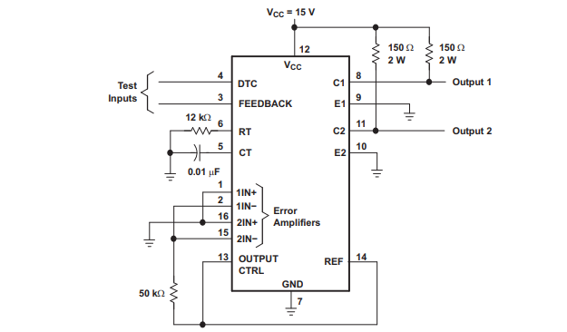
Test circuit

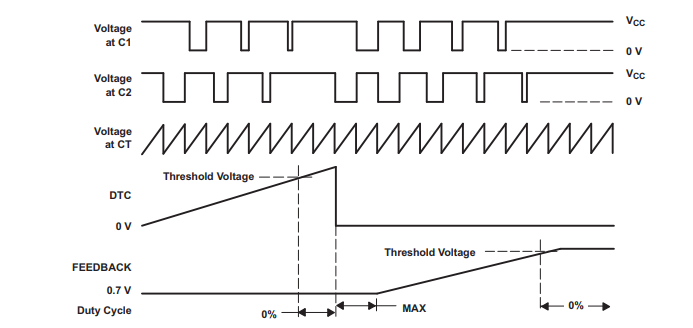
Voltage waveform

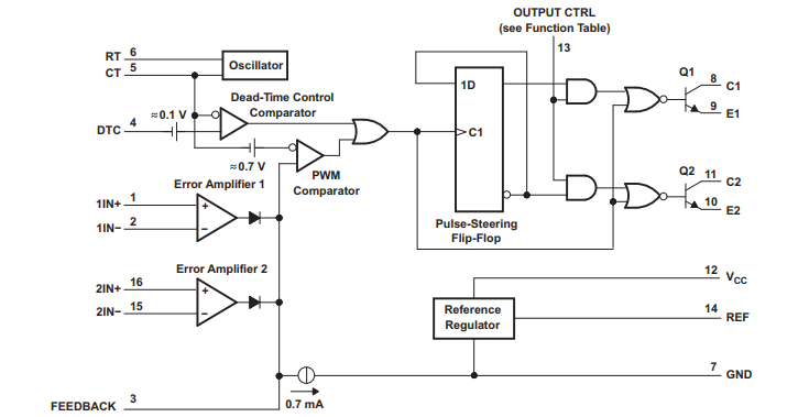
The common-mode voltage range of error amplifiers is from -0.3V to VCC-2v. The dead-time control comparator has a fixed offset and provides about 5% dead-time. The on-chip oscillator can be bypassed by terminating the RT to the reference output and providing a sawtooth input to the CT, or it can drive a common circuit in a synchronous multitrack power supply. Non-output transistors provide common emitter or emitter follower output capability.
Functional block diagram

The TL494 device provides push-pull or single-ended output operations, which can be selected through the output control function. The structure of the device prohibits the possibility of either output being pulsed twice during a push-pull operation. The TL494 device features operating temperatures from 0°C to 70°C. The TL494I device features operating temperatures from -40°C to 85°C.
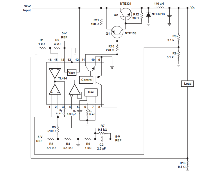
Typical application
