REG101 is a low noise, low difference linear voltage regulator family with low pin current. Available in SOT23-5 and SO-8 packs. It has a very low output noise (generally 23μVrms, VOUT = 3.3V, CNR = 0.01μF), making it ideal for use in portable communication devices. Its new DMOS topology features significant improvements over the previous design, including low voltage (only 60mV at full load) and better transient performance.
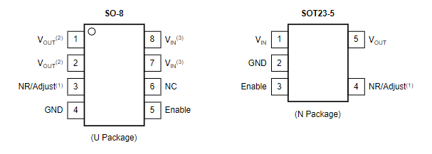
Pin configuration

In addition, no output capacitance is required for stability, unlike traditional low voltage drop regulators, which are difficult to compensate for and require expensive low ESR capacitors greater than 1μF. Typically the pin current is only 500 μA(at I OUT = 100mA), dropping to 10nA in non-enabled mode. Unlike regulators with PNP-pass devices, the static current remains relatively constant under overload changes and power-off conditions.
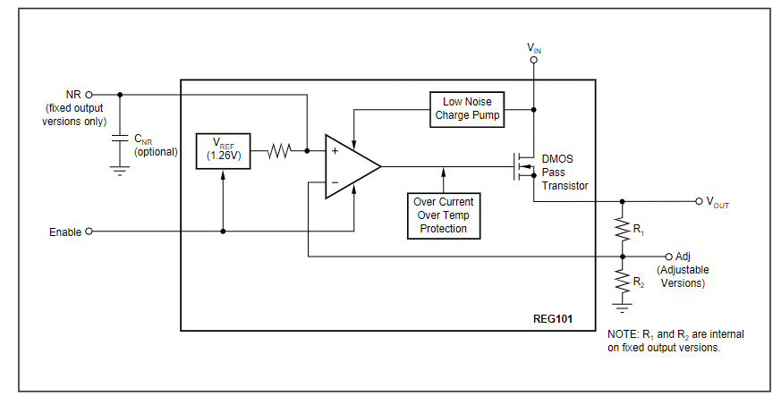
Block diagram

Basic operation
Accuracy is mainly maintained for temperature, line, and load changes. Key parameters are tested in the specified temperature range (-40°C to +85°C). REG101 is well protected, with internal circuitry providing current limitation and protecting loads from damage. The thermal protection circuit prevents the chip from being damaged by excessive temperature.
The REG101 Series LDO(Low Dropout) linear regulators offer a wide selection of fixed output voltage versions and adjustable output versions. The REG101 belongs to the new generation of LDO voltage regulators, which utilize DMOS pass transistors for ultra-low drop performance and are not limited by output capacitance. The ground pin current is maintained below 650 μA under all line, load, and temperature conditions.
All versions have thermal and overcurrent protection, including folding current limits. The REG101 does not require an output capacitor to stabilize the voltage regulator and is stable at most output currents and almost any value and type of output capacitance, up to 10μF or higher.
For applications where the voltage regulator output current drops below a few milliamps, stability can be enhanced by adding 1kΩ to 2kΩ load resistors; Capacitance value less than 10 μF; Or maintain effective series resistance greater than 0.05Ω, including capacitor ESR and parasitic resistance in PCB wiring, solder joints and receptacles. Although no input capacitor is required, it is good practice to use a low ESR capacitor of 0.1μF to input the supply voltage in analog designs. It is suggested to improve ripple suppression by reducing the input voltage ripple.
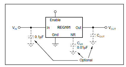
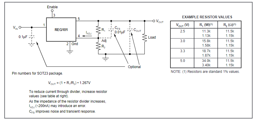
Figure 1 shows the basic circuit connections for the fixed voltage model. Figure 2 shows the connections for the adjustable output version (REG101A) and sample resistance values for some common output voltages. The values of other voltages can be calculated from the equation shown in Figure 2
Figure 1: Fixed voltage nominal circuit REG101.

Figure 2. Adjustable voltage circuit REG101A.
