BTS141 Description
The BTS141 is a high-side power switch for automotive and industrial applications, featuring integrated protection functions. It is based on a n-channel MOSFET and provides over-temperature, over-current, and short-circuit protection. The device is optimized for controlling high-side loads such as motors, relays, and lights in automotive systems, ensuring safe operation by limiting fault conditions.
BTS141 Pinout

Vcc: Supply voltage input pin. This pin connects to the positive power supply, typically in the range of 5.5V to 40V.
OUT: Output pin, connected to the load. This is where the switched power is delivered to the load.
GND: Ground pin. It connects to the system's ground to complete the circuit.
BTS141 Typical Connection

BTS141 Specification
| Specification | Value |
| Switch Type | General Purpose |
| Output Configuration | Low Side |
| Interface | On/Off |
| Load Voltage | 60V (Max) |
| Max Continuous Drain Current | 35A |
| Output Current | 12A |
| Rds(on) | 25mOhm |
| Gate Threshold Voltage (Vgs(th)) | 2V to 4V |
| Gate Drive Voltage | 10V |
| Max Power Dissipation | 80W |
| Operating Temperature Range | -40°C ~ 150°C |
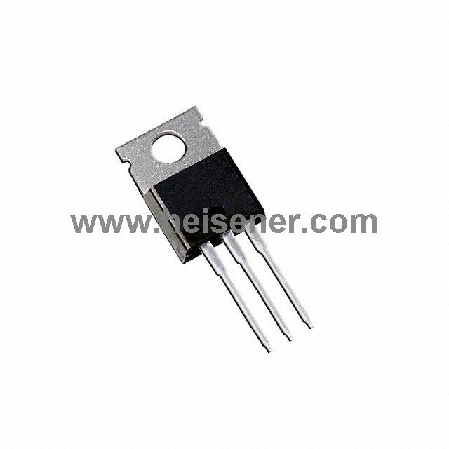
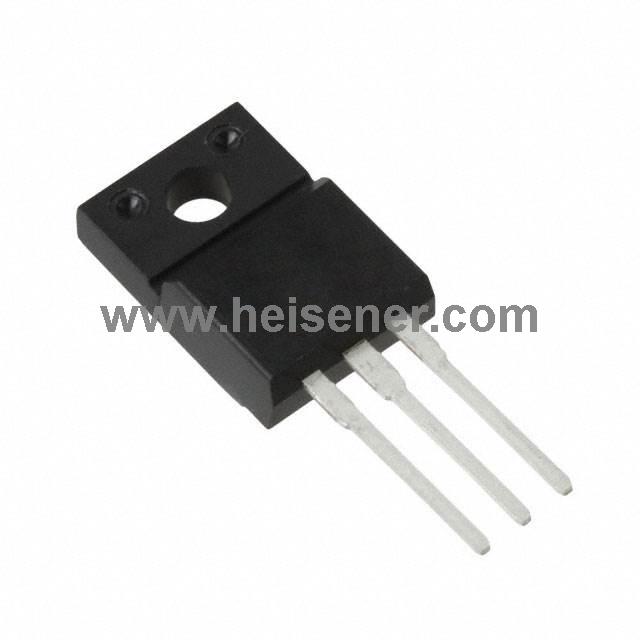
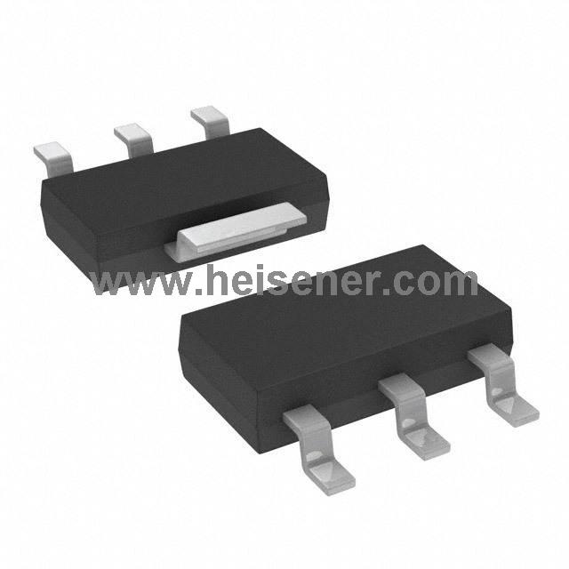
| Package | TO-220-3 |
BTS141 Features
Logic Level Input
Input Protection (ESD)
Thermal shutdown with latch
Overload protection
Overvoltage protection
Current limitation
Status feedback with external input resistor
Analog driving possible
AEC qualified
Green product (RoHS compliant)
BTS141 Applications
All kinds of resistive, inductive and capacitive loads in switching or linear applications
μC compatible power swith for 12V and 24V DC applications
Replaces electromechanical relays and discrete circuits
Power management in communication equipment for reliable operation
Overcurrent and overvoltage protection in power distribution systems
Temperature regulation in heating and cooling systems using microcontrollers
BTS141 Block Diagram


How to Connect BTS141?
When connecting the BTS141 high-side power switch, first, connect the positive terminal of the power supply to the Vcc pin of the BTS141, and the positive terminal of the load to the OUT pin. This allows the BTS141 to control the switching state of the load through the OUT pin. The negative terminal of the load should be connected to the negative terminal of the power supply, completing the current loop. Next, the GND pin must be connected to the common ground of the system.
Then, an appropriate control signal should be connected to the IN pin. After completing these connections, consider adding current and temperature protection. Finally, power on the system and test the switching function to ensure that the BTS141 is properly controlling the load's on/off states.
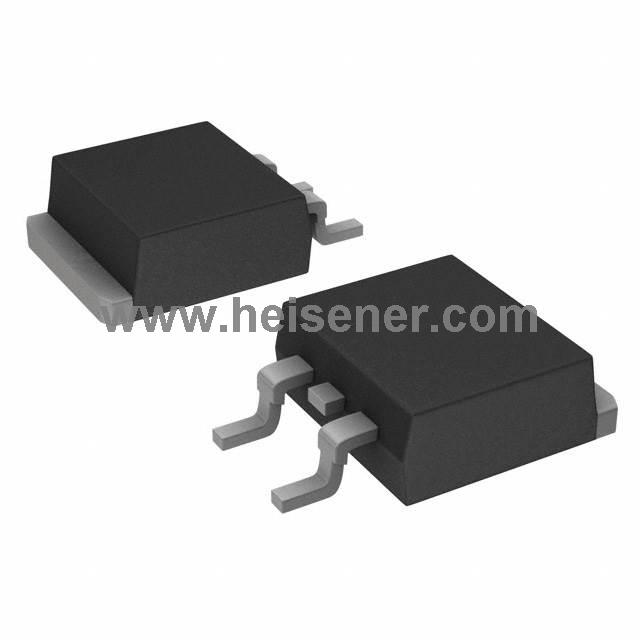
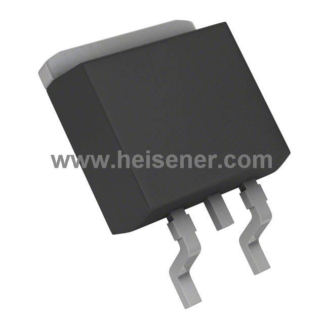
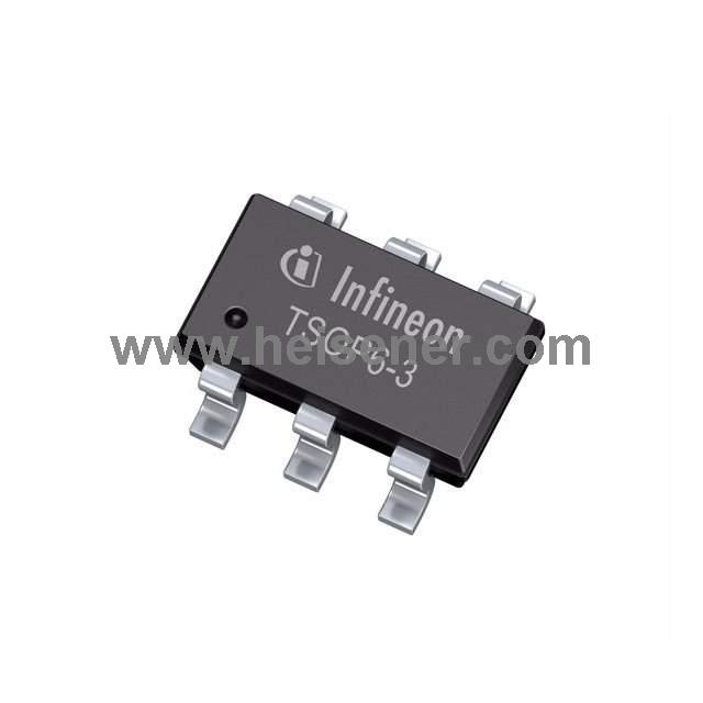
BTS141 Package

BTS141 Alternatives
If you're looking for alternatives to the BTS141, several similar smart high-side power switches can serve as replacements depending on your application needs. Popular options include the BTS134, BTS117, BTS50085 and BTS6143D. They are all excellent choices.
FAQs
How does the BTS141 work?
The BTS141 works by controlling the current flow through a load using its integrated MOSFET. By applying a logic signal to the IN pin, the device switches on or off, allowing current to flow from the Vcc pin to the OUT pin. It acts as a replacement for mechanical relays and discrete circuits, offering precise control and high efficiency.
What types of loads can be controlled by BTS141?
The BTS141 can control a wide range of loads, including resistive loads (e.g., lamps), inductive loads (e.g., motors), and capacitive loads.
What are the advantages of BTS141 over traditional mechanical relays?
The BTS141 offers advantages such as faster switching times, higher reliability, no mechanical wear, and better thermal management compared to traditional mechanical relays. Additionally, it takes up less space and provides more precise control over the load.